-
 SLOPE-ffdm 2.0A precise and effective tool for stability and displacement
analysis of natural and reinforced slopes.Validated through case studies and experiments following major disasters,
including the Kobe and Chi-Chi earthquakes,
as well as landslides triggered by heavy rainfall. -
 SLOPE-ffdm 2.0A precise and effective tool for stability and displacement
analysis of natural and reinforced slopes.Validated through case studies and experiments following major disasters,
including the Kobe and Chi-Chi earthquakes,
as well as landslides triggered by heavy rainfall. -
 SLOPE-ffdm 2.0A precise and effective tool for stability and displacement
analysis of natural and reinforced slopes.Validated through case studies and experiments following major disasters,
including the Kobe and Chi-Chi earthquakes,
as well as landslides triggered by heavy rainfall.
林肯大郡
Case 1: Lin-Can community slope failures in 1997
The collapse of buildings in Lin-Can community due to the failure of an anchored slope with reinforced concrete (RC) girder facing occurred on August 18, 1997. The flawed earth anchor and RC girder facing system were overwhelmed by the driving lateral forces associated with high porewater pressures behind the girder facing induced by typhoon Wendy. The collapse resulted in 28 casualties, with 160 houses completely destroyed and 300 severely damaged.
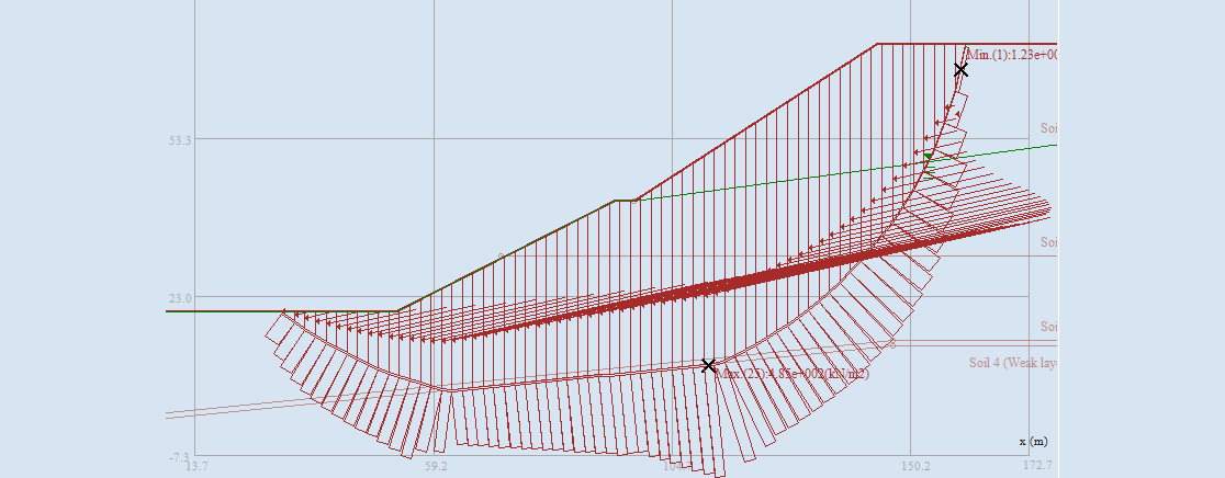
Oversights in accounting for rainfall-induced deterioration of shale strata and porewater pressures in the slope design, along with evidence of anchor malfunction, were the major causes of this failure. A thorough inspection of the worst-case scenario- assessing slope stability and displacement- using analytical tools like SLOPE-ffdm 2.0 could help prevent similar tragedies. Comprehensive slope stability and displacement assessments for the Lin-Can community using SLOPE-ffdm 2.0 are reported in FFDM Software Development Series 19.
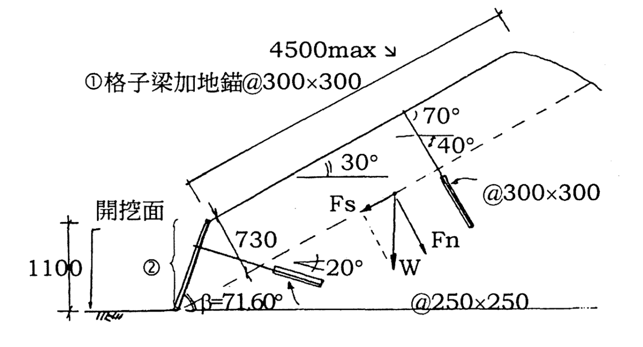
Figure 1 Conceptual design of the anchor and RC girder facing for stabilizing a cut slope consisting of interbedded sandstone and shale.
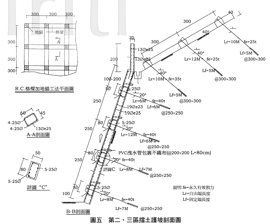
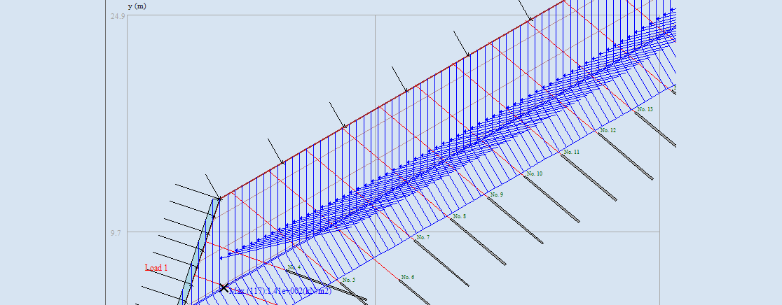
Figure 2 Designed layout of the anchor and RC girder facing system
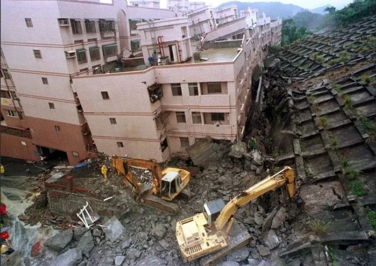
Figure 3 1st- 3rd floors of the buildings adjacent to the slope completely smashed due to the strike of RC girder into the building
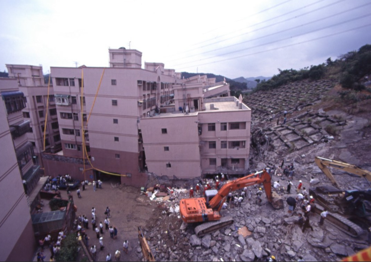
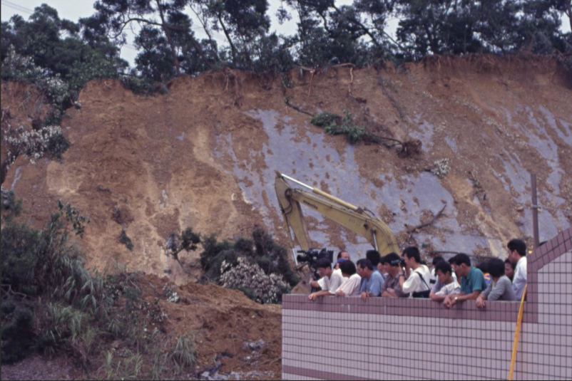
Figure 4 A wider view of the failure site shown in Fig.1.
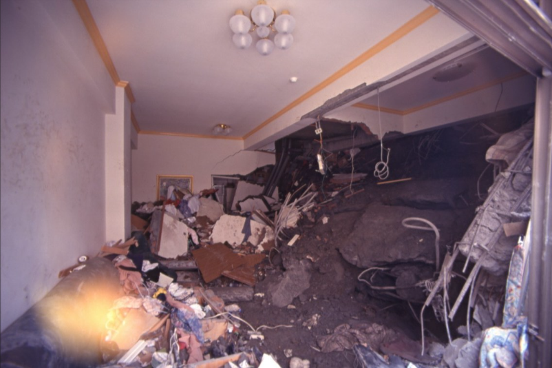
Figure 5 A part of RC girder smashed into the 4th floor of the building.